


Steelcrest Precision
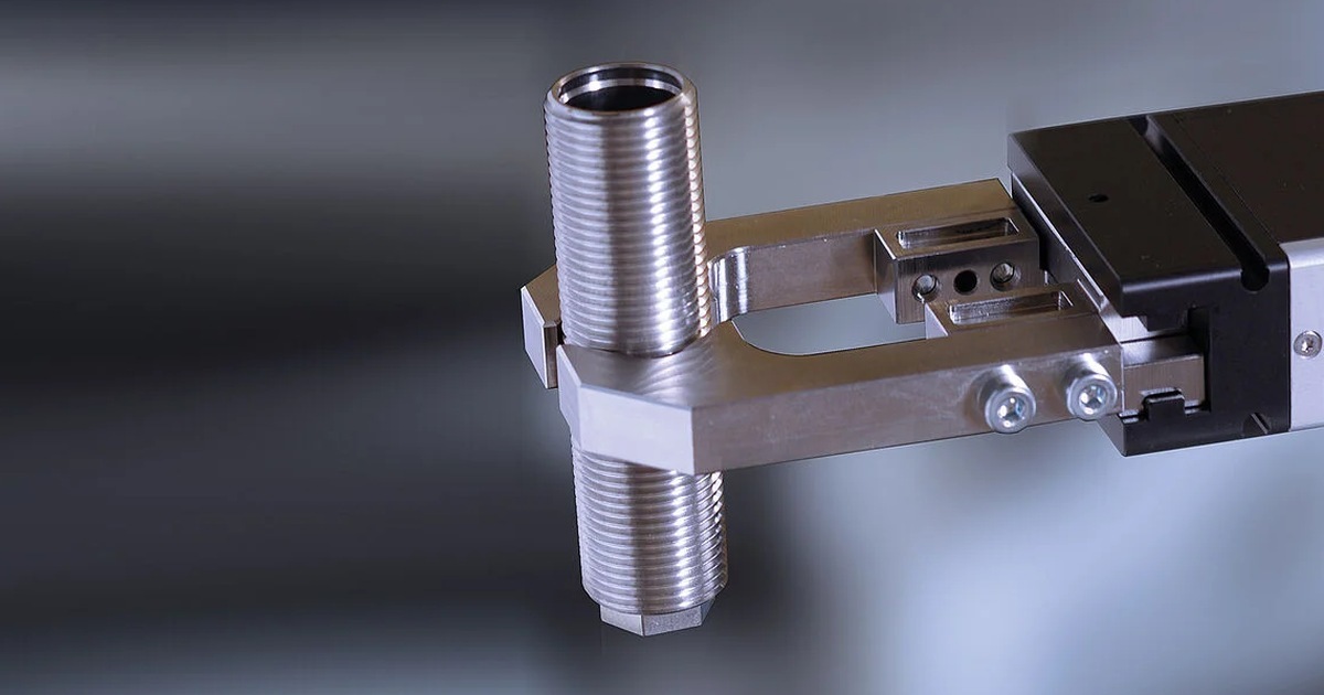

Sourcing machined gripper components comes down to four decisions: the material the grip face is made from, the tolerance that matters at the part and the tolerance that matters at the robot mount, what the drawing has to carry, and whether the shop can run a one-off jaw today and the production set next year.
In an automated cell, the gripper is the last half inch between the robot and the customer's product. The robot, the controller and the conveyor are catalog items that ship on a schedule. The jaw that fits this part, this cell and this takt time is not. It is machined, usually to a drawing the integrator finished last week, and it is the component most likely to be holding up commissioning. This guide is for the integrator or controls engineer placing that work, and it covers what to specify, what to ask the shop, and where the cost and the risk sit. Steelcrest Precision machines gripper components for integrators as part of its precision machining capabilities in Wauseon, Ohio.
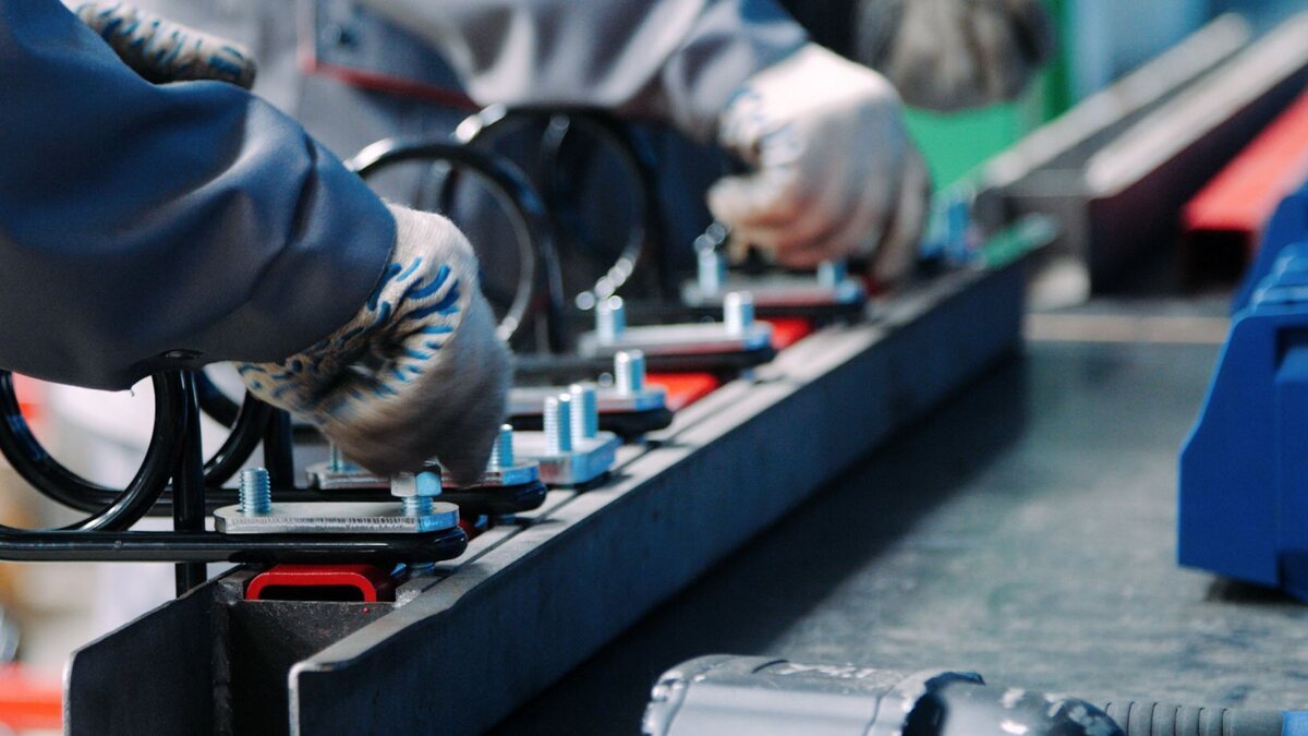
Most of the end-of-arm tooling an integrator buys from a machine shop falls into ten part families. The grip faces and fingers get the attention because they touch the product, but the mounting plates, link plates and sensor brackets are what hold the geometry to the robot flange, and they are machined to the same drawing package.
The practical point for sourcing: these are not catalog parts. An integrator is buying the one geometry that fits one product in one cell, and then buying it again as spares when the grip face wears, or in a revised form when the customer changes the part. A shop that can run the first jaw and the fortieth off the same program is doing more of the integrator's job than one that treats each order as new.
Material is the first decision because it drives everything after it: the tolerance the shop can hold, the surface finish the grip face can take, the wear life, and the weight the robot has to move at the end of the arm. Five materials cover most gripper work, and each one answers a different failure mode.
| Material | Grades | Pick it when | Trade-off |
|---|---|---|---|
| Titanium | Ti-6Al-4V | Speed matters. Roughly 40 percent lighter than steel at comparable strength, so less mass at the tool center point, faster index times and smaller actuators. Non-galling and corrosion resistant. | Work-hardens in the cut. Costs more per pound and per hour than steel. |
| Nickel superalloy | Inconel 625, 718 | The cell runs hot. Forging, heat treat, casting, glass and hot-plate handling. Keeps strength and dimension at temperatures that soften tool steel. | Slow to machine. Heavy. The wrong speeds and feeds cost tooling and parts. |
| Stainless | 304, 316, 17-4 PH | Washdown. Food, beverage, pharmaceutical and medical device cells. 17-4 PH heat treats to high hardness so grip faces keep an edge through millions of cycles. | Heavier than aluminum. 304 and 316 gall against each other without the right finish or coating. |
| Tool steel | A2, D2, 4140 | Abrasive, high-cycle wear faces on dry parts. Hardened and ground inserts that bolt into an aluminum or steel finger. | Rusts without a coating. Hard to rework once heat treated. |
| Aluminum | 6061, 7075 | Bodies, arms, manifolds and brackets where weight matters and the part doesn't touch the product. The default for anything that isn't a grip face. | Wears fast as a contact surface. Needs an insert or anodize where it touches the part. |
| Engineered plastics | Delrin, PEEK, UHMW | Non-marring contact on finished surfaces, glass, painted or plated parts. | Lower stiffness. Creeps under sustained clamp load. |
Two patterns are worth naming. First, the best gripper is often two materials: an aluminum or steel finger with a hardened or titanium insert at the contact point, so the wear part is the cheap part to replace. Second, titanium and Inconel are routine work at some shops and a problem at others. Both work-harden, both hold heat in the cut, and a shop that treats them as specials will quote long and deliver late. Steelcrest runs both as standard work; see titanium machining and Inconel and nickel alloy machining for how.
Two different tolerances live on a gripper drawing, and they are usually confused. The first is at the grip face, where the jaw meets the product: this is about repeatability, surface finish and whether the part is held square. The second is at the robot mount, where the tool plate meets the flange: this is about putting the grip point where the program thinks it is, every time the tool is swapped or rebuilt.
For most work, a standard precision tolerance of ±0.001 in on the mounting and locating features is what the drawing should call out. Dowel holes and datum faces that set the tool center point are where the tighter work goes; select features held to ±0.0002 in are available when the application needs them, and most do not. Over-toleranced gripper drawings are common, and they are the fastest way to turn a two-week part into a six-week part.
A gripper that is a few thousandths off at the mount does not fail on day one. It drops a part every few hundred cycles, and nobody traces it back to the jaw.
Surface finish on the grip face is a separate specification and should be on the drawing. A serrated face for dry steel, a ground face to 8 Ra for a precision locating jaw, a polished or coated face for a finished part. If the drawing says nothing, the shop will leave a milled finish, and the integrator will find out at the first part drop whether that was right.
Three reasons, and the integrator controls two of them. The geometry is finalized late, because it depends on the customer's part and the cell layout, both of which move during the build. The quantity is small, often one set plus spares, so the work does not get the priority that a production run gets at a shop set up for volume. And the material is often hard or exotic, which puts the part on the shop's slowest machine behind its longest queue.
The sourcing rule
Place the proof-of-concept jaw and the production set with the same shop, and ask for the program, fixture and first article to stay on file. The second order then runs off a proven process instead of starting over, and the spares order six months later is a phone call, not a new RFQ.
The part the integrator does not control is the shop's setup. A gripper set that needs turning, milling, grinding and wire EDM is four operations, and at a shop that only mills, it is also two outside vendors, two trucks and two inspection reports to reconcile. Steelcrest runs those operations under one roof, with grinding and wire EDM on the same inspection record as the milling, and heat treating in house with furnaces to 2100F. No minimum order quantity means the one-off jaw and the production set come from the same shop on the same process.
A complete gripper drawing package gets quoted faster and machined right the first time. Six items cover most of the questions a shop would otherwise have to call about.
For how the drawing turns into a part, From RFQ to Finished Part walks the process step by step.
Four questions sort the field. Can the shop run the materials the application demands as routine work, not as a special? Does the geometry get verified on a CMM or optical system with a report that ships with the part? Will the program, fixture and first article stay on file for the spares order? And can the shop take the whole routing, including grinding, EDM and heat treat, without sending the part out?
Beyond those, a few items matter for specific cells. Integrators building for defense customers need a shop that is ITAR registered. Integrators building for aerospace or medical customers will want to see the quality system: Steelcrest is ISO 9001:2015 certified and runs processes compliant with AS9100 while working toward certification. The inspection equipment, the documentation that ships with the part and the certifications are on the quality and certifications page.
Aluminum for bodies and arms, hardened tool steel or 17-4 PH stainless for wear faces, titanium where weight at the end of the arm matters, Inconel for hot cells, and 304 or 316 stainless for washdown. Many fingers combine two: an aluminum finger with a hardened or titanium insert at the contact point.
A standard precision tolerance of ±0.001 in on mounting and locating features covers most gripper work. Hold the dowel pattern and datum face that set the tool center point tighter if the application needs it; select features can be held to ±0.0002 in. Leave everything else at a general tolerance to keep cost and lead time down.
Yes, if the shop has no minimum order quantity. Steelcrest machines one-off proof-of-concept jaws and the production set that follows on the same process, and keeps the program and fixture on file so spares run off a proven setup.
Titanium is roughly 40 percent lighter than steel at comparable strength, so a titanium jaw lowers the mass at the tool center point. That means faster index times, smaller actuators and less wear on the robot. It is also non-galling, non-magnetic and corrosion resistant, which suits high-cycle pick-and-place and long-reach jaws.
Usually. Making the contact surface a bolt-in insert means the part that wears is the part you replace, and the finger behind it stays in service. It also lets you change the grip-face material or finish without redesigning the gripper.
Gripper components, build to print
Send the drawing and the model if you have one. Steelcrest will quote the jaw, the set and the spares as one routing, in the material the cell actually needs.
Send us a drawing